GPIO (General Purpose Input / Output)
🟠 What is a general purpose input output (GPIO) of the MCU
GPIO
GPIO stands for general purpose input/output. It is a type of pin found on an integrated circuit that does not have a specific function.
While most pins have a dedicated purpose, such as sending a signal to a certain component, the function of a GPIO pin is customizable and can be controlled by the software.
It can work as:
📥 Input (reads logical signals, such as from a button)
📤 Output (controls something - LED, relay, motor)
🔄 Sometimes - both as an input and as an output (push-pull)
Pin
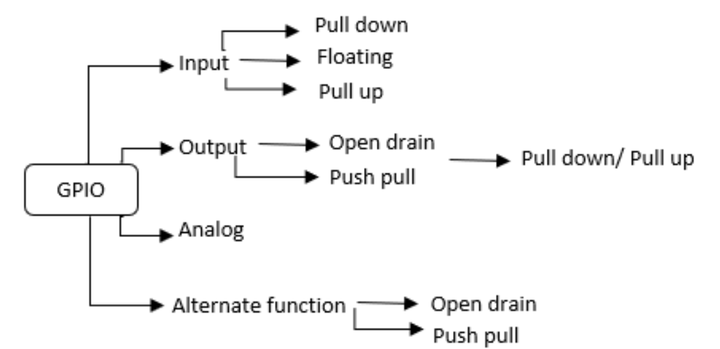
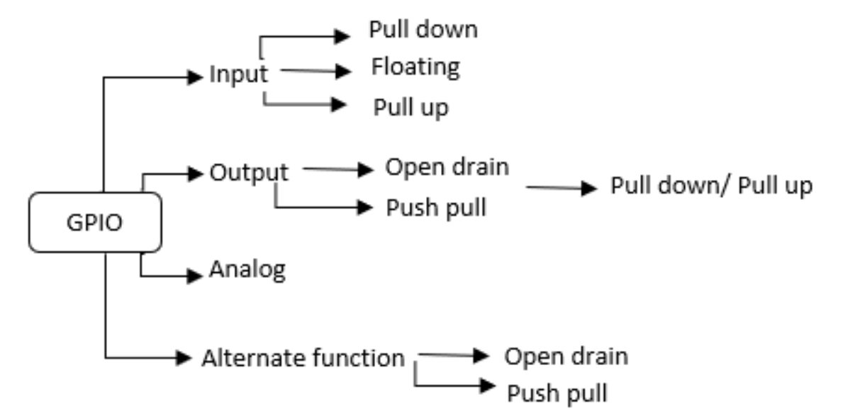
Pin Mode : Each port bit of the general-purpose I/O (GPIO) ports can be individually configured by software in several modes:
- input or output
- analog
- alternate function (AF). Pin characteristics :
- Input : no
pull-upand nopull-downor pull-up or pull-down - Output :
push-pulloropen-drainwith pull-up or pull-down capability - Alternate function : push-pull or open-drain with pull-up or pull-down capability.
GPIO Design
Each GPIO pin of the microcontroller consists of three key components:
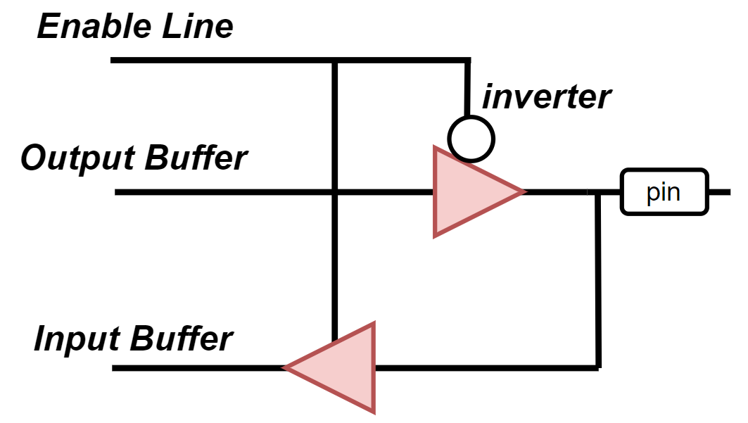
- Enable Line
- Configures the pin mode:
input,output,alternate function,analog, etc. - Controls the activation of internal pull-up resistors
- Enables/disables input/output buffers and logic enable
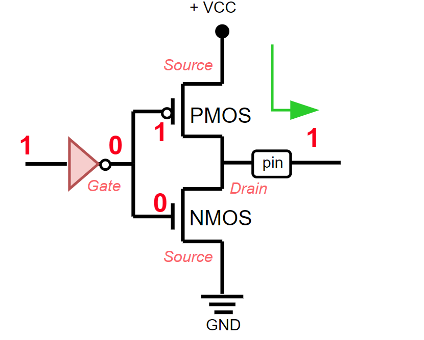
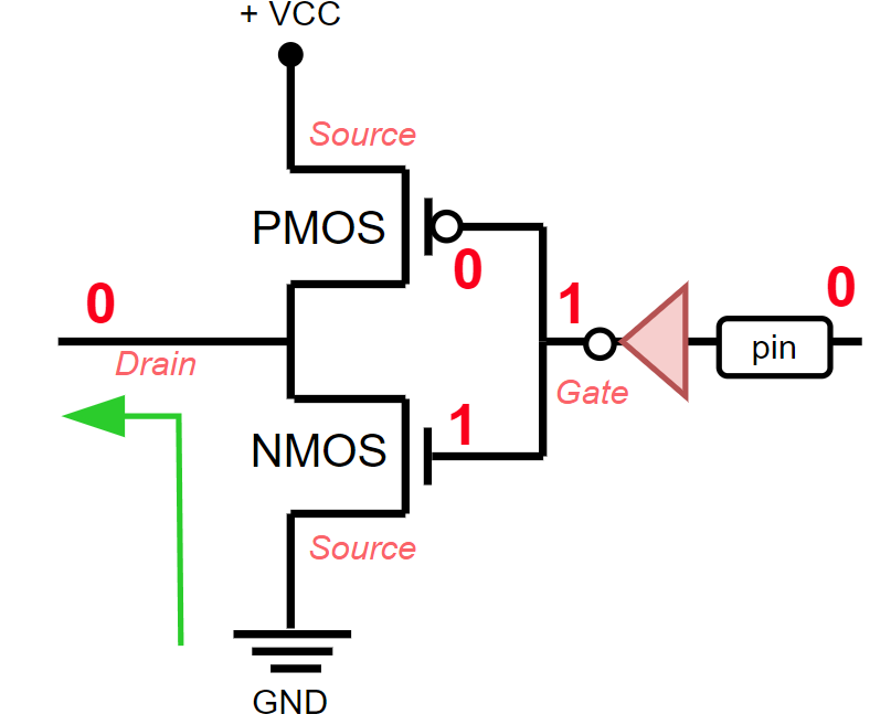
- Output Buffer
- It is a combination of two transistors (PMOS + NMOS)
- In Push-Pull mode both can work
- In Open-Drain only
NMOSis active - Allows to output logic levels to an external pin
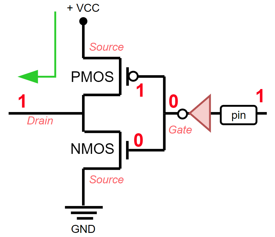
When the signal 0 comes out, control goes through the NMOS transistor and no logical one is supplied to the pin.

1 comes out, control goes through the PMOS transistor and a logical one is supplied to the pin.
- Input Buffer
- Monitors the signal level on the pin
- Can be enabled or disabled - for example to disable reading during output
- Used to read logic level or generate interrupts
When a 0 signal is received on the pin, control passes through the NMOS transistor and goes to GND
1 signal is received on the pin, control passes through the PMOS transistor and is powered from +VCC
⚙️ GPIO Modes
- By default all GPIOs on most microcontrollers are configured in Input mode.
- In this mode they are not connected to either Vcc or GND - the pin is in the High Impedance (Hi-Z) state.
- This means that the GPIO is not "involved" in the circuit's operation, but may be subject to noise and flow currents, especially if the input is left "floating".
| Mode | Description | Example |
|---|---|---|
| Input | Reading signal from outside | Button, sensor |
| Input Pull-Up | Input with pull-up to Vcc (internal resistor) | Button to GND |
| Input Pull-Down | Input with pull-up to GND | Button to Vcc |
| Output Push-Pull | Normal output (0 or 1) | LED, relay |
| Output Open-Drain | Only "0", "1" — via external resistor | I²C, external bus |
| Analog | ADC/DAC is used on the output | Temperature sensor, audio |
| Alternate Function | Used by peripherals (SPI, PWM, UART) | SPI, I²C, PWM |
If we wanted to use some Pin as an input, we would use either .into_pull_up_input(), .into_pull_down_input() to tell the chip to expect the system voltage (3.3 volts) to be present or absent, and react if that changes.
// RP2040 (Rust embedded-hal, hi-Z)
    _pin_28.into_pull_down_input(); // Set GPIO 28 as input with pull-down
    _pin_28.into_floating_input(); // Set GPIO 28 as floating input
    _pin_28.into_pull_up_input(); // Set GPIO 28 as input with pull-up

    _pin_28.into_pull_up_disabled(); // Disable pull-up on GPIO 28
    _pin_28.into_pull_down_disabled(); // Disable pull-down on GPIO 28

    _pin_28.into_push_pull_output(); // Set GPIO 28 as push-pull output
Output
Push-Pull
- GPIO uses two transistors: PMOS (to supply "1") and NMOS (to supply "0").
- In Push-Pull mode, the pin can actively:
- Supply the line with logical 1 (Vcc) via PMOS
- Supply logical 0 (GND) via NMOS
- This is the standard mode for driving LEDs, relays and other loads.
Open-Drain
- In this mode, GPIO can only short the pin to ground (0) via NMOS.
- Internal PMOS is missing or disabled → you cannot apply "1" directly.
- When GPIO is driven to logic "1" → transistor is off and pin becomes floating.
- To make the line to be logic "1", a pull-up resistor is used:
- Internal (enabled by software if available)
- External (usually 4.7k–10k Ohm to Vcc)
Useful when When need a common bus with many devices connected to it. (All participants can only "pull down" to avoid conflict)