PWM (Pulse Width Modulation)
🟠 How to handle pulse width modulation
PWM (pulse width modulation) is used to control the power supplied to the load.
🔸 Classic method - reducing the voltage through a rheostat or potentiometer.
🔻 Disadvantage: inefficient, since part of the energy is lost as heat.
🔸 PWM method - supplying voltage in short pulses with a fixed amplitude.
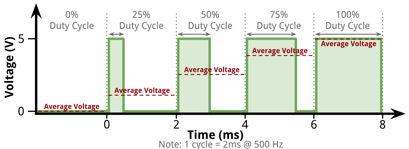
Instead of changing the voltage, the duty cycle changes:
- More on time → more power
- Less on time → less power
This control method is efficient and causes almost no losses.
Brief
- mainly used to control the power supplied to the device.
- in some cases it can be used to transmit information for configuring the device.
- has a low power loss and the ability to digitally/software control.
It has 2 main parameters
- Frequency (switching frequency,
Hz), - Duty cycle (percentage of time in "HIGH" state, from
0%to100%).
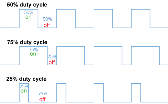
Duty cycle
- Percentage of time during which the signal is active
- signal with 20% duty cycle is active 20% of the time
- signal with 50% duty cycle is active 50% of the time
- signal with 80% duty cycle is active 80% of the time
- The duty cycle can be set or controlled in
3 main ways- Manual method (Use various knobs or sliders)
- Automatic (for example, using feedback on the output voltage in a pulse power supply)
- Software (using some kind of intelligent system that changes the pulse width depending on external logic or parameters)
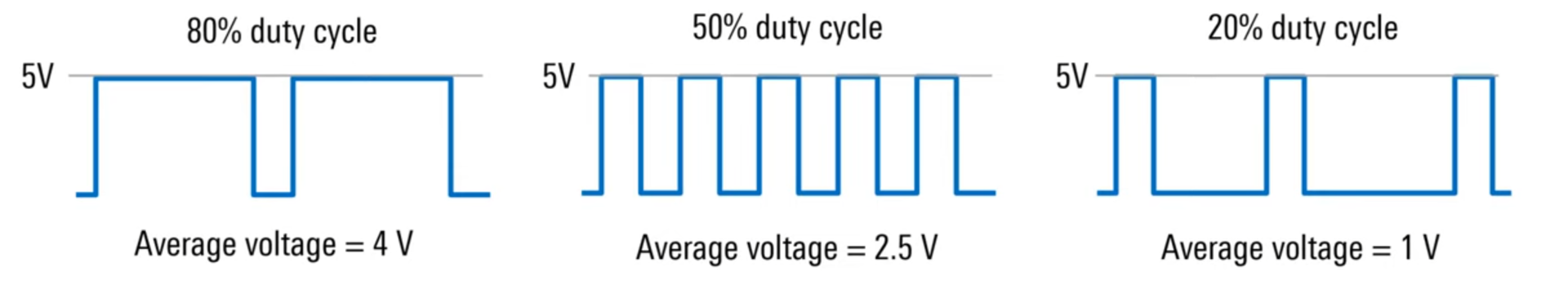
Average voltage level
PWM - often used to vary power by changing the average voltage level across a load.
- average load =
peak voltage(5V) *duty cycle(20%) = 1V
Switching Frequency
- Switching frequency, which is defined as the reciprocal of the time between the leading edges of the voltage pulses.
- The required switching frequency depends on the load or application area
- can be from
10Hz to severalkHz - for applications where faster or more precise control is required - higher switching frequencies are used
- but in most applications the switching frequency is fixed
- can be from
- Signals can have the same duty cycles, but different switching frequencies
Examples of PWM Systems
| System | Description |
|---|---|
| 1. Visual Devices | ● Screen brightness control (high frequency to avoid flickering) ● RGB LED color control |
| 2. Audio | ● Digital to analog conversion via filtering ● Use efficient Class D amplifiers |
| 3. Switching Power Supplies (SMPS) | ● The basis of switching converters ● Use MOSFETs to switch pulses |
| 4. DC Motors | ● Fan or pump speed control ● Lower duty cycle → lower speed ● Inertia smooths out operation |
| 5. Servos | ● PWM sets position, not speed ● Pulse width corresponds to deviation from neutral ● Power is supplied via a separate channel |
| 6. Inverters (DC→AC) | ● Generating an alternating signal from PWM pulses |
| 7. Chargers | ● Charging batteries (including from solar panels) ● PWM regulates average voltage to prevent overcharging and reverse current |
🧱 Embedded Rust approach:
- HAL library (e.g.
stm32f1xx-hal,rp2040-hal,esp32-hal) provides API to peripherals. PWMis usually implemented via timers (TIM).- Each
PWMchannel is assigned aGPIOpin and a timer.
🔨 General flow of creating PWM in Rust
- Access
PWMslices (Slices::new) - Configure
PWM7(it controlsGPIO15pin) - Configure channel B of this
PWM(channel connected toGPIO15) - Connect
GPIO15toPWMas output - In the loop, change the duty cycle value to get the breathing effect
💡 Implementation: RP2040
use rp2040_hal::{self as hal, pwm::Slices};

    // PWM Slices Init
    let pwm_slices = Slices::new(pac.PWM, &mut pac.RESETS);
    // Get 7th slice (controls GPIO 14 (A) and GPIO 15 (B))
    let mut pwm_slice = pwm_slices.pwm7;

    pwm_slice.set_ph_correct(); // Phase correct mode = smoother signal
    pwm_slice.set_top(255); // 8-bit duty cycle precision
    pwm_slice.enable(); // enable slice

    // Get channel_b from 7th slice
    let mut channel_b = pwm_slice.channel_b;
    // Make channel_b output to 15th pin
    let _pin = channel_b.output_to(pins.gpio15);

    let mut duty: i16 = 0;
    let mut step: i16 = 1;

    loop {
        let _ = channel_b.set_duty_cycle(duty as u16);
        timer.delay_us(1000);

        duty += step;
        if duty >= 255 || duty <= 0 {
            step = -step;
        }
    }
🧰 Tips for working with PWM
- Do not exceed the frequency - some devices work up to
1-10 kHz. - PWM resolution depends on the timer (8/10/12/16 bit).
- For multi-channel PWM use different channels of the same timer or timers.
- Use a logic analyzer or oscilloscope for visualization.
- Timers often work asynchronously - glitches at startup are possible.
- For silent PWM (LED) use frequencies >
1 kHz.
Read other posts?