I2C (Inter-Integrated Circuit)
A technical introduction to the I2C - low-speed two-wire master-slave serial protocol.
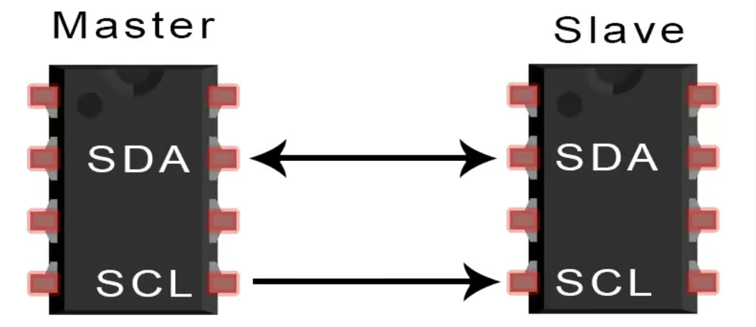
I2C is widely used for short-distance data transmission over a data bus (SDA) with a clock synchronization line (SCL).
I2C
I2C - Inter-Integrated Circuit
The most common protocol for transmitting data over short distances.
Synchronous master-slave protocol.
Both the master and slave can transmit data.
Usually operates in half-duplex (at any given moment, only send or receive data can occur) mode at different clock frequencies.
Message exchange occurs in frames.
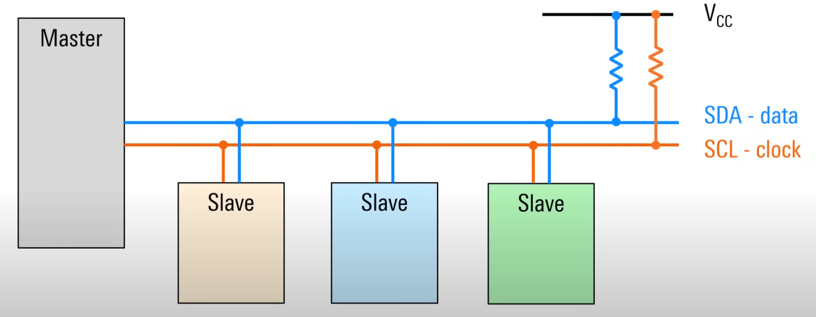
Two wires are used -
- SCL - serial clock signal
- SDA - data bus
In addition, the wires are connected to the Vcc supply using one pull-up resistor.
SDA Frame Format
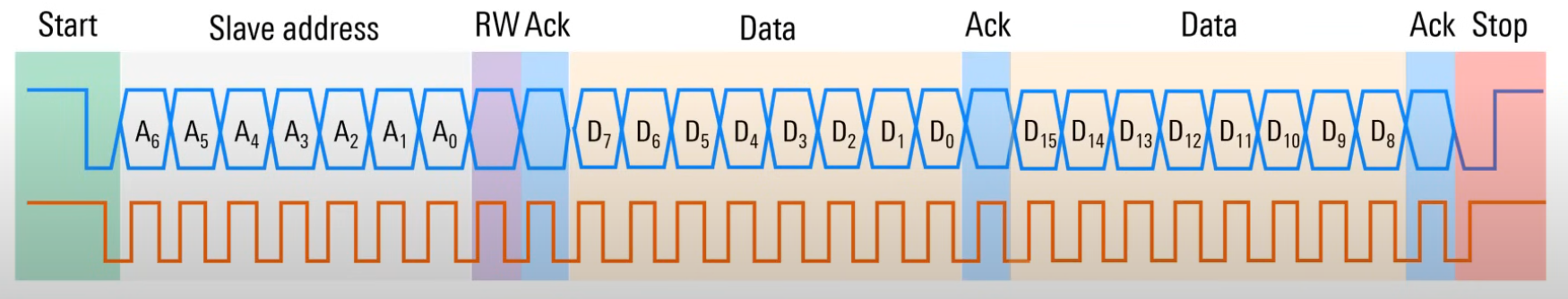
- master capture SDA bus with
start condition - via SDA is sent
slave addresswhich master wants to communicate - after address is specified operation bit
R/W. master wants to read or write data - after operation bit slave sends
Arc, indicating its presence - if
Arcis received from slave then master sendsuseful data - after data slave sends
Arc, thus indicating that data is received - communication is stopped by
stop condition
Start Condition
As in UART, the idle state - for SDA and SCL - is high(1)
- the
start conditionoccurs when the node first pullslow(0)SDA, and then pullslow(0)SCL. Pulling down in this order occurs to capture the data bus. - after the data bus is captured - the node becomes the master. This prevents other nodes from capturing the bus and reduces the risk of conflicts.
Slave Address
- specifies which slave-node the master wants to communicate with.
- each node on the bus has a
unique fixed addressusually7 bitswith MSB first (most significant bit is one) - addresses can be hardcoded but sometimes they can be configured via wires
R/W bit
Immediately after the slave address comes the read or write bit and is set by the master.
0- the master wants to write data to the slave1- the master wants to receive data from the slave
Ack bit
An acknowledge bit is sent by the receiver each time a byte of data is received
0- acknowledgement (ACK)1- negation (NACK)
The I2C ishigh(1)inidle, so if the receiver does not respond by actively switching the line tolow(0)level, it will be perceived as a failure.
After the address and each byte of data received (8-bit), there is an acknowledgement Arc.
Data bits
After the address bit come the data bits that are exchanged between the master and slave.
- often this data is a memory or register address in the slave
- data is always transmitted
8-bitwide and MSB first
In most cases, multiple data transfers occur, with each8-bithaving to be acknowledged separately
Stop Condition
Mechanism to say that the last byte of data has been sent. Stop condition -
- the SCL line goes
high(1)and stays there - then SDA goes
high(1)and stays there too
- to transmit data bytes, the SDA line goes
low(0)only when SCL islow(0)level - if the SDA line goes
low(0)when SCL ishigh(1)- this is thestop condition.
After the stop condition - the bus becomes inactive and there is no clock signal.
And any node on the bus can use the start condition to take over the bus and start a new communication.
Synchronization of data and clock pulses
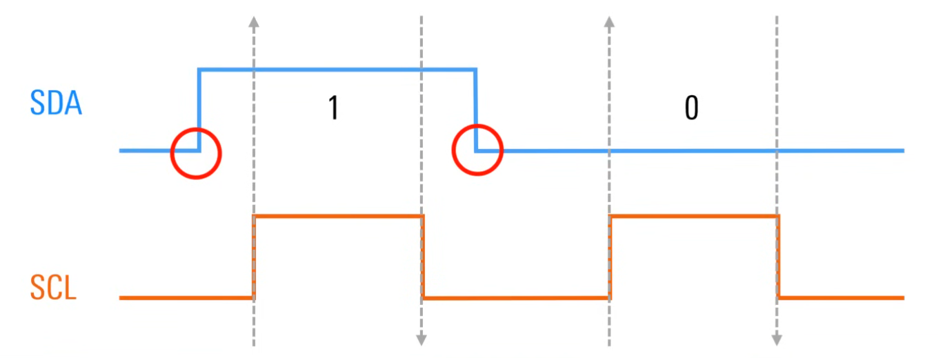
- data is always read in the
middleof the clock pulse and never in the intervals between them.
This is necessary, because switching SDA at ahigh(1)level of the SCL signal would mean thebeginningorendof the data transfer. (start / stop condition) - it turns out that SDA switches (0-1) only at a
low(0)level on SCL
Open Drain
- usually SDA and SDA are
high(1)because each of them is connected to the power supply (+Vcc) via a pull-up resistor, with one resistor per line, not one node.
- Each I2C device contains a logic device inside that can open and close the drain
- When the drain is
closed, the SDA or SCL lines are in alow(0)state because now it is connected to ground (GND) - When the drain is
opened, the line goeshigh(1)because now its connected to the power supply (+Vcc)
When the lines are not in use, they are high(1) voltage, that is why I2C is called an open drain system
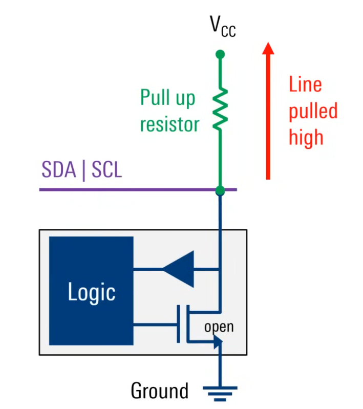
Pull- Up resistor
- Pulling down to low(0) faster than pull up to
idlehigh(1) - the
higherthe resistor resistance, the more time is needed to raise the line, and this in turn limits thespeed of the bus. - the
lowerthe resistor resistance, the faster the communication occurs, but at the same timemore energyis required
- usually the values of pull-up resistors for I2C are in the range of
1kOm-10kOm
Modes \ Speed
pull-up resistor values are one of the factors limiting the maximum bus speed.
I2C speeds are usually called modes
I2C supports several speeds:
- standard (100 kbps),
- fast (400 kbps),
- fast+ (1 Mbps). There are also experimental implementations with even higher speeds, but they are usually rarely used.