SPI (Serial Peripheral Interface)
A technical introduction to the SPI - low-speed four-wire master-slave full-duplex serial protocol.
SPI is widely used as a faster alternative to UART/I2C for transferring data between an intelligent controller and a less intelligent peripheral device.
SPI
SPI - Serial Peripheral Interface
A protocol in which there is one leader (master or controller) and one or more slaves (or peripheral device)
Usually operates in full-duplex (both nodes transmit data simultaneously)
Message exchange occurs in frames.
SPI has no agreement on frame formats, number of transmitted bits and voltage levels
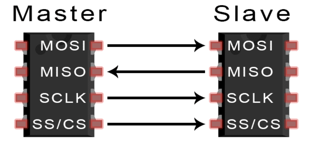
SPI Design
- the
CS(Chip Select)/SS(Slave Celect) channel is used to select the slave - clock signals on the
SCLKline are used for synchronization MOSI(Master Out Slave In) data is transmitted from the master to the slaveMISO(Master In Slave Out) data is transmitted from the slave to the master
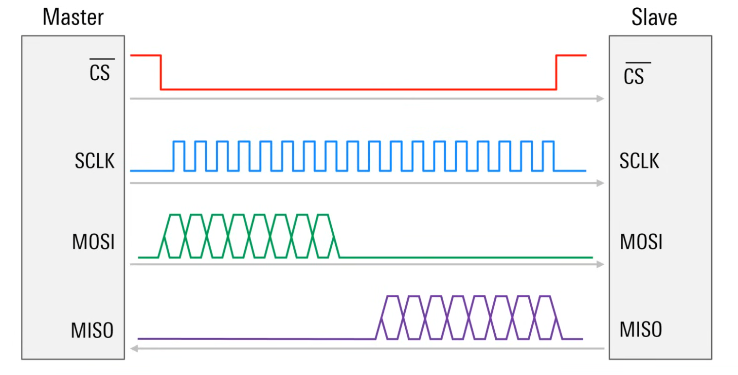
- switch the SC line
low(0), indicating that information will be transferred to this slave - starts the SCLK signal
- transfer occurs on (MOSI / MISO)
- switch CS back to
high(1)
SCLK
- after CS is set to
low(0), the master starts generating a clock signal - this allows the slave to not have a clock signal, and used master clock - the clock is usually in
Mhz - the clock in this case tells the slave at what moment to
start readingthe voltage level on the data line.
The clock signal in SPI by default idle can be in a low(0) or high(1) state, and data can be read on the rising or falling edge of the signal.
MOSI
Used to send data from a master to a slave
After CS is pulled low(0) and SCLK is enabled, MOSI is used to transfer data from the master to the slave as an 8-bit bytes, where the first bit can be the least significant bit (LSB, MSB).
Multiple bytes can be transferred while CS is low(0).
MISO
Used to send data from a slave to a master
- Often used to respond to data received from MOSI.
- Since only the master can hold the clock, it must know exactly how many bytes the slave wanted to send over MISO.
This can be afixed number, or a specified number that the master will respond to the slave's request with.
SPI Adjustment
Clock Polarity
CPOL - the clock signal generated by the master can be:
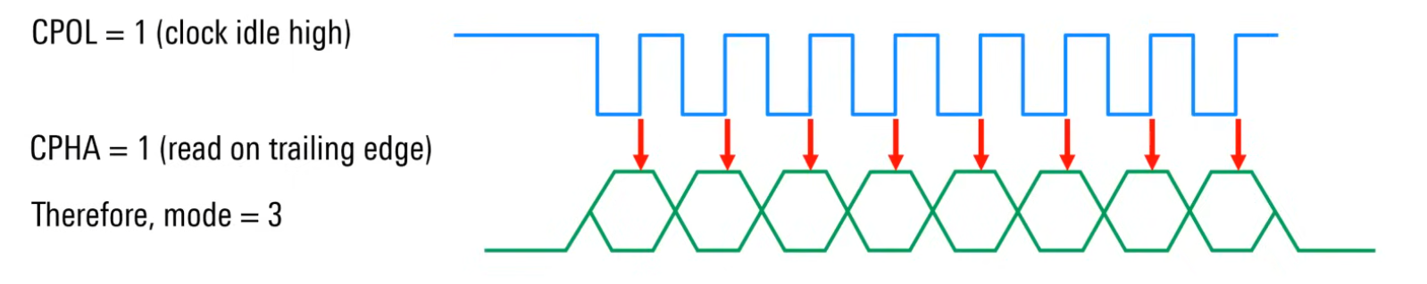
low(0)at idle, active athigh(1)level (CPOL = 0."non-inverted") (Leading (first edge)-rising)high(1)at idle, active atlow(0)level (CPOL = 1."inverted") (Leading (first edge)-falling) CPOL indicates which of these options is used
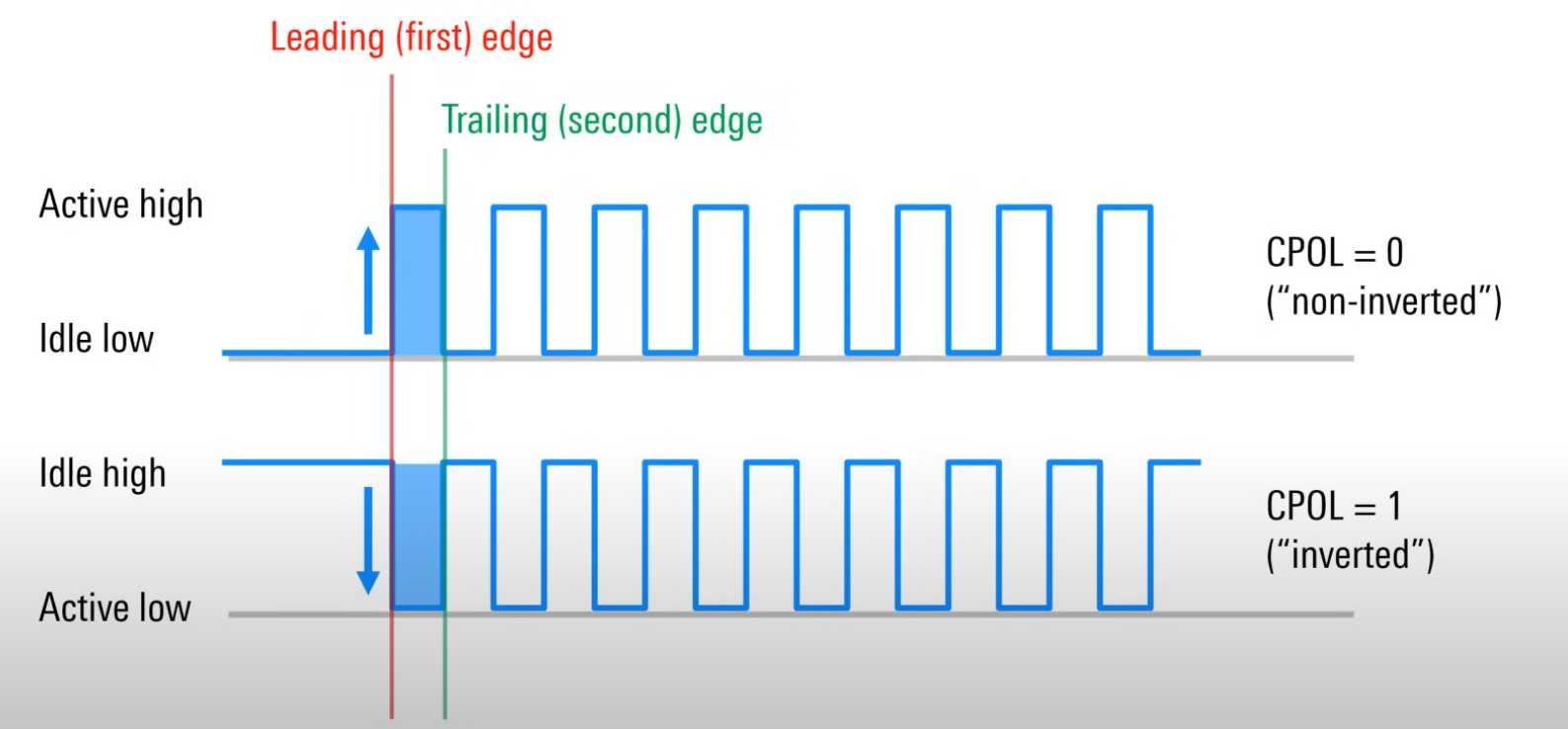
For both types of clock pulse polarity, you can focus on
- leading edge of the clock pulse (Leading (first edge))
- trailing edge of the pulse (Trailing (second)edge)
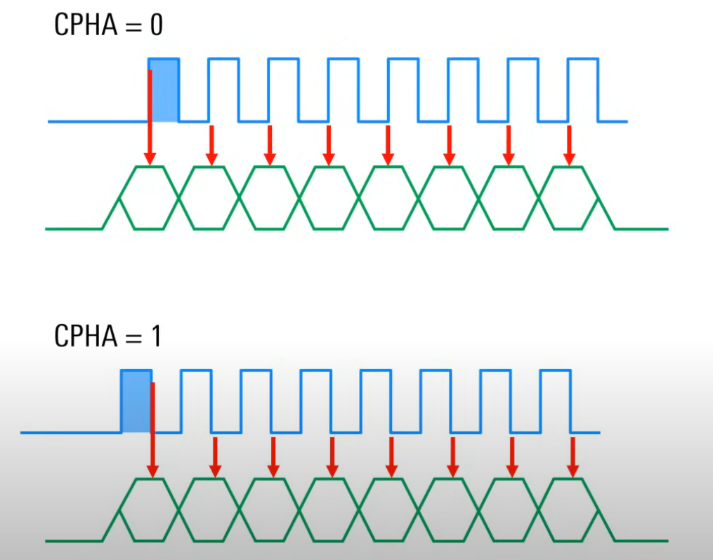
Clock Phase
CPHA - determines on which edge the nodes will read data
CPHA - 0means that data will be read on therisingedge of each clock signalCPHA - 1means that data will be read on thefallingedge of each clock signal
SPI Mode
The operation of the master and slave must be coordinated via the SPI operating mode.
The mode is an integer combination of CPOL and CPHA
| Mode | CPOL | CPHA |
|---|---|---|
| 0 | 0 | 0 |
| 1 | 0 | 1 |
| 2 | 1 | 0 |
| 3 | 1 | 1 |
|
Multi-slave configuratuion
- Independent Slaves
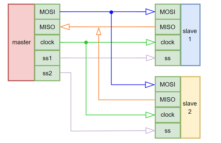

- In this configuration, the master has a
separate CSline for each slave. - The remaining channels are shared on the bus.
The method is relatively simple until there are many slaves.
- Cooperative Slaves / Daisy Chain

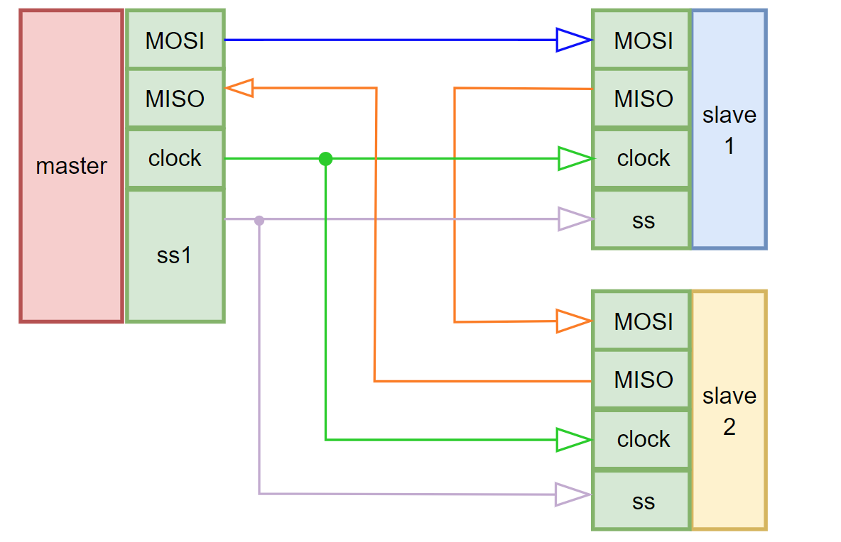
- With this configuration, the master has
only one CS line, which is used by all slave devices. - With this configuration, data on MOSI is always sent to the
first slave, and data transfer to another slave occurs through MISO of the first slave that received data on MOSI, and so on to transfer data to the next slave. - If a slave wants to send data to the master through its MISO channel, it also sends it to the
next slavein the chain, and so on until it reaches thelast one, whose MISO channel is not connected to the next slave, but is connected to themaster.
The cooperation mode reduces the required number of lines, but it is more complex and may not be supported by some devices.