UART (Universal Asynchronous Receiver / Transmitter)
A technical introduction to the UART - low-speed two-wire asynchronous multi-duplex serial protocol.
UART The earliest serial protocol. Still commonly used in modern electronics.
UART
UART - Universal Asynchronous Receiver / Transmitter
-
Simple, inexpensive, and easy to implement
-
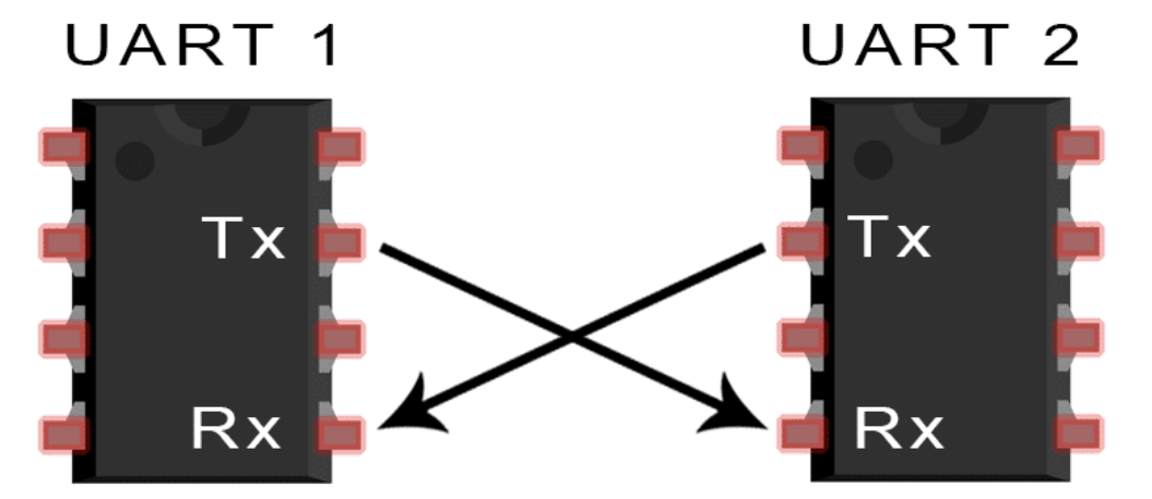
UART works by transmitting and receiving data over two wires:
TX(transmit) andRX(receive). -
Asynchronous means that the transmitter and receiver
do not share a common clock signal- this simplifies the protocol due to the lack of a separate synchronization line.- BUT this imposes its own requirements on the transmitter and receiver -
the speed must be the same - Speed is measured in bauds (bits per second).
- Baud rate must be configured the same on both sides. Common speeds include
4800,9600,19200,38400,57600,115200baud and higher.
- BUT this imposes its own requirements on the transmitter and receiver -
-
In addition, both nodes must use a fixed message structure and know how many bits are in each frame and what they mean.
-
Can connect only two nodes. For this, two data transmission wires are used, which connect the transmitter of one node to the receiver of the other and vice versa.
In this configuration, data exchange can be:
simplex- only in one direction (TX -> RX)half-duplex- at the same time, either transmission or reception of data can occur. (Tx -> RX, RX -> TX)full-duplex- both nodes transmit data simultaneously. (TX <-> RX)
UART Frame Format
high(1)level consists ofstartandstopbitsdatabitsparitybit (optional)
- When data is not transmitted (
idle) the line is inhigh(1)state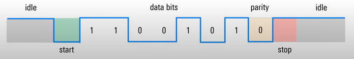

Start / Stop
The transmitter must inform the receiver that the data is ready to be transmitted.
The start bit is a transition from idle high(1) to low(0) state.
After sending the data, there is a stop bit which means that the sending is complete.
The stop bit either transitions from low(0) to high(1) state, or simply leaves the state high(1).
Data bit
Useful information comes immediately after the start bit (there can be from 5 to 9, but most often 7-8 bits)
- These bits are usually transmitted with the least significant bit at the beginning (
LSB first)- 7-bit ASCII 'S' = 1010011
- LSB order = 1100101
Parity bit
Used to detect any errors in the transmitted message
located between the last data bit and the stop bit
- the value of the bit depends on the type of parity used
- even parity - the number of
1in the data frame must be even.
When sending1100101- the parity bit will be0because there is already an even number of1. - odd parity - the number of
1must be odd.
When sending1100101- the parity bit will be1because there must be an odd number of1in the frame. - can detect only one error, if there are more, then this bit will not detect them.